


Introduction
Modern engineering projects require accurate product designs, reliable performance, and efficient development processes. Before manufacturing a component or assembling a complex product, engineers must understand its geometry, materials, structural behavior, and operating requirements. Computer-Aided Design (CAD) and Finite Element Analysis (FEA) are important technologies that help engineers address these challenges.
CAD enables engineers to create detailed digital models of components, products, and mechanical assemblies. FEA helps evaluate how these designs may respond to forces, pressure, temperature changes, vibration, and other physical conditions.
Together, CAD and FEA can support better design decisions, identify potential problems early, and reduce the need for repeated physical prototypes. Understanding these technologies can help businesses improve engineering workflows and develop products that meet their performance requirements.
What Is CAD/FEA Design and Analysis?
CAD/FEA Design and Analysis combines digital product modeling with computer-based engineering simulation.
Computer-Aided Design (CAD) is used to create, modify, and document digital representations of components and assemblies. Engineers can use CAD software to define dimensions, geometry, material assignments, and relationships between different parts.
Finite Element Analysis (FEA) is a numerical simulation method used to estimate how a physical structure or component behaves under specified conditions. It divides a model into smaller elements and uses mathematical calculations to approximate its response to applied loads and boundary conditions.
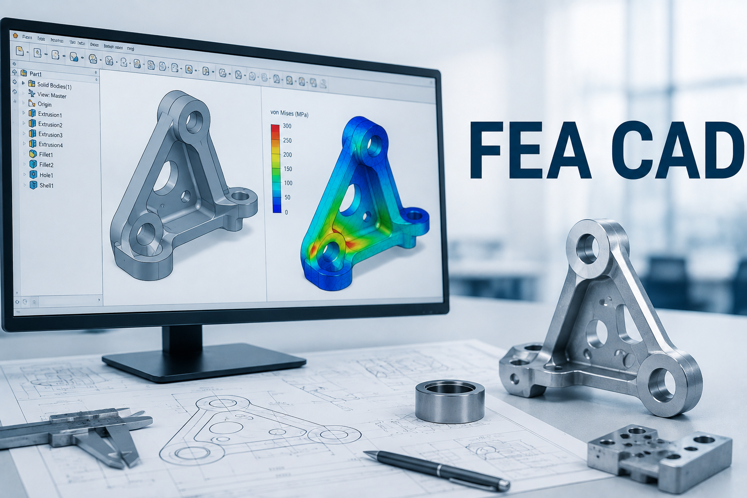
For example, an engineer designing an industrial machine bracket can create its geometry in CAD and then use FEA to estimate stress and deformation under an expected load.
The results can help identify areas that may require design changes before the component is manufactured.
The reliability of these results depends on the quality of the model, material properties, boundary conditions, mesh selection, and validation process.
Why Is CAD Important in Engineering Design?
CAD has become an essential part of modern product development because it allows engineers to create and modify designs digitally.
1. Accurate Digital Modeling
CAD software allows engineers to define dimensions, geometric features, and relationships between components.
Detailed models help communicate design requirements and provide a foundation for manufacturing drawings and further engineering analysis.
2. Faster Design Modifications
Product requirements may change during development. Engineers may need to adjust dimensions, replace components, or explore alternative configurations.
Digital modeling makes these modifications easier to manage than repeatedly creating physical prototypes for every design change.
3. Improved Assembly Planning
Complex products often contain many interconnected components.
CAD assemblies help engineers examine component positioning, identify potential interference, and evaluate how parts fit together.
This can help detect certain design issues before manufacturing or assembly begins.
4. Better Technical Documentation
CAD tools can support the preparation of engineering drawings, dimensions, and other technical documentation.
Clear documentation helps communicate design intent to manufacturing teams, suppliers, and other project stakeholders.
What Is Finite Element Analysis?
Finite Element Analysis is an engineering simulation technique used to approximate the physical behavior of components and structures.
In a typical FEA workflow, engineers prepare a digital model, define material properties, specify loads and boundary conditions, create a mesh, and solve the mathematical equations governing the problem.
The resulting calculations can provide estimates of quantities such as stress, displacement, strain, temperature distribution, or natural frequencies, depending on the analysis type.
Structural Analysis
Structural FEA evaluates how a component may respond to applied forces, pressures, and constraints.
Engineers can use it to investigate stress concentrations, deformation, and structural performance under specified loading conditions.
Thermal Analysis
Thermal FEA estimates temperature distributions and heat transfer under defined thermal conditions.
It can support the design of electronic enclosures, industrial equipment, and components exposed to elevated temperatures.
Vibration and Modal Analysis
Modal analysis estimates the natural frequencies and mode shapes of a structure.
These results can help engineers understand potential vibration behavior and identify areas requiring further investigation.
Fatigue Analysis
Fatigue analysis evaluates the potential for damage under repeated or fluctuating loads.
Depending on the method and available data, engineers can estimate fatigue life or compare alternative designs.
Each analysis type requires appropriate assumptions, material data, and validation to produce meaningful results.
Benefits of Combining CAD and FEA
Using CAD and FEA together can improve several stages of engineering development.
1. Early Identification of Design Problems
Simulation can help engineers investigate areas where stress, deformation, or temperature may exceed acceptable limits.
Identifying potential issues early can make design changes less expensive than discovering them after manufacturing.
2. Reduced Dependence on Physical Prototypes
Physical testing remains important, but simulation can help evaluate multiple design alternatives before producing prototypes.
This may reduce the number of prototype iterations required for certain projects.
However, simulation does not eliminate the need for physical testing when testing is required to verify performance, safety, or compliance.
3. Improved Material Selection
Engineers can compare suitable materials by evaluating their properties under the expected operating conditions.
Material selection must also account for manufacturing methods, environmental exposure, durability, cost, and other practical requirements.
4. Better Weight and Structural Optimization
Many products need to balance strength, weight, cost, and manufacturability.
CAD and FEA can help engineers explore alternative geometries and evaluate whether material can be removed or redistributed without compromising required performance.
5. More Informed Engineering Decisions
Digital models and simulation results provide additional information for evaluating design alternatives.
When supported by sound engineering judgment, these results can help teams make more informed decisions throughout product development.
Applications of CAD/FEA Design and Analysis
CAD and FEA are used across several engineering disciplines.
Automotive engineering: Engineers use CAD to develop vehicle components and assemblies, while FEA can help evaluate structural strength, vibration, thermal behavior, and crash-related performance.
Aerospace engineering: Digital modeling and simulation support the development of lightweight structural components and complex assemblies.
Industrial machinery: CAD and FEA can help evaluate machine frames, brackets, shafts, housings, and other components exposed to mechanical loads.
Consumer products: Engineers can model product enclosures and mechanisms and investigate their expected performance under relevant operating conditions.
Electronics: CAD supports enclosure and mechanical component design, while thermal analysis can help evaluate heat distribution and cooling requirements.
Robotics: Engineers use digital models to develop robot structures, mounting components, and mechanical assemblies. Simulation can help assess stiffness, deformation, and other relevant design considerations.
The appropriate tools and analysis methods depend on the product, materials, operating environment, and engineering objectives.
The CAD/FEA Design and Analysis Workflow
A structured process helps engineers develop useful models and reliable simulation results.
Step 1: Define Design Requirements
Engineers establish the component's function, dimensions, operating conditions, material constraints, and performance objectives.
Clear requirements provide the foundation for the design and analysis process.
Step 2: Create the CAD Model
A three-dimensional model is developed using the selected CAD software.
The model should represent the geometry relevant to the engineering problem without introducing unnecessary complexity.
Step 3: Assign Material Properties
Engineers select appropriate material properties based on reliable data.
These may include elastic modulus, density, thermal conductivity, yield strength, and other properties required for the chosen analysis.
Step 4: Prepare the FEA Model
The CAD geometry is prepared for simulation. Engineers define the mesh, boundary conditions, loads, contacts, and other necessary parameters.
Incorrect assumptions at this stage can produce misleading results.
Step 5: Run the Simulation
The solver calculates the model's response to the defined conditions.
Engineers review the results and check whether the solution behaves consistently with the physical problem.
Step 6: Evaluate and Optimize the Design
Simulation results are compared with engineering requirements and acceptable performance limits.
If necessary, engineers modify the design and repeat the analysis.
Step 7: Validate the Results
Mesh convergence checks, analytical comparisons, experimental testing, or other suitable validation methods help establish confidence in the simulation.
The level of validation depends on the complexity and consequences of the engineering application.
Common Challenges in CAD/FEA Projects
Despite their advantages, CAD and FEA require careful technical execution.
Incorrect boundary conditions: Unrealistic constraints or loading assumptions can distort the results.
Poor mesh quality: An unsuitable mesh may fail to capture important stress gradients or geometric details.
Inaccurate material properties: Incorrect input data can reduce the reliability of the simulation.
Complex geometry: Detailed models may require additional preparation and computational resources.
Misinterpretation of results: Simulation outputs must be evaluated in context rather than treated as automatically correct.
Manufacturing limitations: A design that performs well in simulation may still be difficult or expensive to manufacture.
Addressing these challenges requires engineering expertise, appropriate software, and a structured verification process.
Conclusion
CAD/FEA Design and Analysis plays an important role in modern product development by combining digital modeling with engineering simulation. CAD helps engineers create detailed product designs, while FEA provides estimates of structural, thermal, and other physical responses under defined conditions.
Together, these technologies can help identify potential problems, compare design alternatives, and improve engineering decisions before manufacturing begins.
Successful implementation depends on accurate models, suitable material data, realistic assumptions, and appropriate validation. When used correctly, CAD and FEA can support more efficient product development and help engineers meet technical requirements.

 Arabic
 French
 Spanish
 Portuguese
 Deutsch
 Turkish
 Dutch
 Italiano
 Russian
 Romaian
 Portuguese (Brazil)
 Greek